nRF21L01 Module
Radio Frequency
The nRF24L01+ transceiver module is designed to operate in 2.4 GHz worldwide ISM frequency band and uses GFSK modulation for data transmission. The data transfer rate can be one of 250kbps, 1Mbps and 2Mbps.
Power consumption
The module supports programmable output power viz. 0 dBm, -6 dBm, -12 dBm or -18 dBm and consumes unbelievably around 12 mA during transmission at 0 dBm
SPI Interface
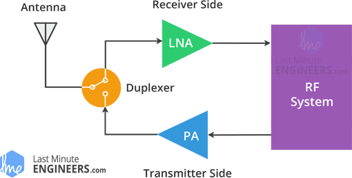
What is PA LNA?
The PA stands for Power Amplifier. It merely boosts the power of the signal being transmitted from the nRF24L01+ chip. Whereas, LNA stands for Low-Noise Amplifier. The function of the LNA is to take the extremely weak and uncertain signal from the antenna (usually on the order of microvolts or under -100 dBm) and amplify it to a more useful level (usually about 0.5 to 1V)
How it work?
RF Channel Frequency
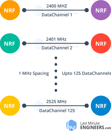
The nRF24L01+ transceiver module transmits and receives data on a certain frequency called Channel. Also in order for two or more transceiver modules to communicate with each other, they need to be on the same channel. This channel could be any frequency in the 2.4 GHz ISM band or to be more precise, it could be between 2.400 to 2.525 GHz (2400 to 2525 MHz).
Each channel occupies a bandwidth of less than 1MHz. This gives us 125 possible channels with 1MHz spacing. So, the module can use 125 different channels which give a possibility to have a network of 125 independently working modems in one place.
The channel occupies a bandwidth of less than 1MHz at 250kbps and 1Mbps air data rate. However at 2Mbps air data rate, 2MHz bandwidth is occupied (wider than the resolution of RF channel frequency setting). So, to ensure non-overlapping channels and reduce cross-talk in 2Mbps mode, you need to keep 2MHz spacing between two channels.
RF channel frequency of your selected channel is set according to the following formula:
Freq(Selected) = 2400 + CH(Selected)
For example, if you select 108 as your channel for data transmission, the RF channel frequency of your channel would be 2508MHz (2400 + 108)
Higher Output Power
Setting maximum output power can also improve the communication range. The nRF24L01+ lets you choose one of the output power viz. 0 dBm, -6 dBm, -12 dBm or -18 dBm. Selecting 0 dBm output power sends stronger signal over the air.
0dmB equal 1mW
Multiceiver Network
The nRF24L01+ provides a feature called Multiceiver. It’s an abbreviation for Multiple Transmitters Single Receiver. In which each RF channel is logically divided into 6 parallel data channels called Data Pipes. In other words, a data pipe is a logical channel in the physical RF Channel. Each data pipe has its own physical address (Data Pipe Address) and can be configured. This can be illustrated as shown below.
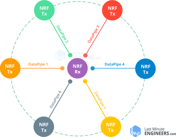
To simplify the above diagram, imagine the primary receiver acting as a hub receiver collecting information from 6 different transmitter nodes simultaneously. The hub receiver can stop listening any time and acts as a transmitter. But this can only be done one pipe/node at a time.
Enhanced ShockBurst Protocol
The nRF24L01+ transceiver module uses a packet structure known as Enhanced ShockBurst. This simple packet structure is broken down into 5 different fields, which is illustrated below.
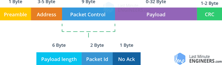
The original ShockBurst structure consisted only of Preamble, Address, Payload and the Cyclic Redundancy Check (CRC) fields. Enhanced ShockBurst brought about greater functionality for more enhanced communications using a newly introduced Packet Control Field (PCF).
This new structure is great for a number of reasons. Firstly, it allows for variable length payloads with a payload length specifier, meaning payloads can vary from 1 to 32 bytes.
Secondly, it provides each sent packet with a packet ID, which allows the receiving device to determine whether a message is new or whether it has been retransmitted (and thus can be ignored).
Finally, and most importantly, each message can request an acknowledgement to be sent when it is received by another device.
nRF24L01+ Automatic Packet Handling
Now, let’s discuss three scenarios to get a better understanding of how two nRF24L01+ modules transact with each other.
Transaction with acknowledgement and interruptThis is an example of positive scenario. Here the transmitter starts a communication by sending a data packet to the receiver. Once the whole packet is transmitted, it waits (around 130 µs) for the acknowledgement packet (ACK packet) to receive. When the receiver receives the packet, it sends ACK packet to the transmitter. On receiving the ACK packet the transmitter asserts interrupt (IRQ) signal to indicate the new data is available.
Transaction with data packet lostThis is a negative scenario where a retransmission is needed due to loss of the packet transmitted. After the packet is transmitted, the transmitter waits for the ACK packet to receive. If the transmitter doesn’t get it within Auto-Retransmit-Delay (ARD) time, the packet is retransmitted. When the retransmitted packet is received by the receiver, the ACK packet is transmitted which in turn generates interrupt at the transmitter.

Transaction with acknowledgement lostThis is again a negative scenario where a retransmission is needed due to loss of the ACK packet. Here even if the receiver receives the packet in the first attempt, due to the loss of ACK packet, transmitter thinks the receiver has not got the packet at all. So, after the Auto-Retransmit-Delay time is over, it retransmits the packet. Now when receiver receives the packet containing same packet ID as previous, it discards it and sends ACK packet again.
This whole packet handling is done automatically by the nRF24L01+ chip without involvement of the microcontroller.
Ok, Let's coding.
You can refer to
GitHub - nRF24/RF24: OSI Layer 2 driver for nRF24L01 on Arduino & Raspberry Pi/Linux Devices


Comments
Post a Comment